| The N2PK VNA has been described by Pat Hawker, G3VA, in the
Sept. 2004 issue of RadCom (Radio Society of Great Britain).
In addition to the VNA in the Sept 2004 isssue of RadCom, you
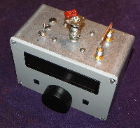
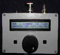
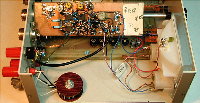
will also see a reference to the "The N2PK power / SWR meter" which
is described below.
Pat devotes almost one page of his four page column in this
issue to the VNA and features the VNA block diagram.
The above RadCom reference is not available online.
Ian White, GM3SEK, devoted his entire Oct. 2004 RadCom "In
practice" to the N2PK VNA:
http://www.ifwtech.co.uk/g3sek/in-prac/61_62_radcom_oct04.pdf
The Oct. 2004 RadCom front cover also featured a photo of Ian's VNA.
A highly processed photo of the VNA PCB around the RF DDS also
appeared on the cover of the RSGB 2003-2004 Annual Report.
Bob Cerreto, WA1FXT, wrote an article about his N2PK VNA in the
January 2006 Bacon Bits Quarterly Newsletter:
http://www.fpqrp.com/BBITS/BBQ0106.PDF
Bob's article also appeared in The QRP Quarterly, Spring 2006,
published by QRP ARCI.
Giancarlo Moda, I7SWX, wrote an article in the April 2004 issue
of Radio Rivista, an Italian publication, titled "IL VECTOR NETWORK
ANALYZER DI N2PK".
The N2PK VNA is also discussed in the 4th Edition of "Low-Band
DXing" by John Devoldere, ON4UN, and is available from ARRL and RSGB.
See Section 3.6.9 on page 11-34. However, there are some corrections
needed:
- The URL to this website is incorrect. It should be
"http://n2pk.com".
- To my knowledge, there is no commercial effort
underway.
- In Section 3.6.10, there is an implication that the N2PK VNA,
with its narrowband detector, suffers from "alien-signal overload" in
the same manner and extent as other instruments which typically have
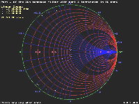
wideband detectors. A simulated test using the N2PK VNA,
approximating John's 160m large antenna measurement with a strong AM
BC "alien" or "ambient" signal present, yielded the following
result:

As can be seen, the N2PK VNA is essentially bulletproof up to
+10 dBm of ambient signal @ 110 kHz away from the desired signal. If
needed for extreme cases, higher levels of ambient immunity can be
secured by combinations of various means: a) increased (desired)
generator signal, b) added attenuation between the bridge and the
detector, c) a high-pass, bandpass, or notch filter between the
bridge and the detector, or d) a similar filter between the bridge
and the antenna. If the instrument is calibrated with the filter in
place, then even quite substantial amplitude or phase errors in the
filter will not affect the measurement.
Most of these means can not be used with other instruments
commonly available to the amateur radio community due to design
limitations.
As the frequency difference between the desired signal and
ambient signal is reduced, the ambient immunity of the N2PK VNA is
expected to decrease as the ambient signal falls within the detector
bandwidth, which is 5 Hz at 3 dB down for the orginal "slow" detector
and rate dependent for the "fast" detector. Time permitting, more
about this may be covered at a later date. However, it is not a
particularly pressing issue as no ambient signal problems with the
N2PK VNA have been reported to date.
|


